

[Part 2 of the 4/3-Way Valve Centre Configuration Series]
Industrial presses, material handling tools, construction equipment, tractors, and loaders often require a valve that holds the load for a long duration while lowering power consumption. The tandem-centre configuration of a 4/3-way (directional control) valve provides this capability by internally connecting the pressure port directly to the tank port while blocking both work ports. This article explains how the valve works, why it is used, and when it should be selected.
Construction
The cross-sectional view and symbol of a 4/3-way tandem-centre hydraulic valve are shown in Figures 1(a) and 1(b). The valve has four ports and three switching positions. It can be actuated manually or electrically via solenoids. When no other actuating force is present, the valve snaps to the centre position via springs.
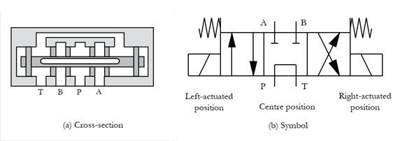
Figure 1 | 4/3-way tandem-centre valve
Neutral Position
In the neutral (centre) position of the hydraulic valve, the actuator ports (A and B) are internally blocked, and the pressure port (P) is connected to the tank port (T), as shown in Figure 1. Blocking both actuator ports hydraulically locks the associated actuator, allowing it to hold the connected load for a longer duration. At the same time, with the pump port connected to the tank port, the pump can unload to the tank at minimum pressure, thereby reducing power consumption.
Principle of Operation
The positions, connections, and functions of the valve in the left-actuated, centre, and right-actuated positions are given in Table 1.
Table 1 | A hydraulic 4/3-way tandem-centre valve
| Left-actuated position | Centre (Neutral) position | Right-actuated position |

| Valve Ports: P – Pressure port T – Tank port A & B – Working ports (Imagine the ports are fixed while valve positions change) | ||
| P -> A B -> T | A, B -> Blocked P -> T | P -> B A -> T |
| A connected cylinder extends | The cylinder is locked | The cylinder retracts |
Logic Diagram
Figure 2 highlights the concepts for the valve’s neutral position, as presented in the previous section.
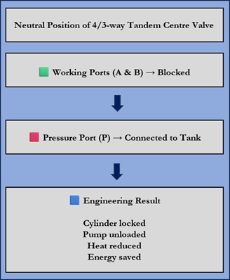
Figure 2 | Logic diagram illustrating the fundamental principles of tandem-centre position.
Why Choose a Tandem Centre Valve?
In a tandem-centre 4/3-way valve, ports A and B are blocked in the neutral position. Consequently, the associated hydraulic cylinder can trap pressure when the valve is shifted to its neutral position. Therefore, the cylinder can be locked in position for an extended period. At the same time, the pump is unloaded to the tank, dropping the pump pressure and reducing heat buildup and energy consumption. These two characteristics make the tandem-centre configuration one of the most widely used neutral spool arrangements in industrial hydraulic systems employing fixed-displacement pumps.
Key Engineering Concepts
Let us start by becoming familiar with the key terms and conditions that apply to actuators controlled by tandem-centre valves before we move on to their applications.
Pump Unloading: In the neutral position of the valve, a pump bypasses fluid to the tank at near-atmospheric pressure, reducing heat and saving energy when work is paused.
Cylinder Locking: It is a state of a loaded hydraulic cylinder that remains completely stationary due to trapped pressure on both sides of the cylinder piston.
Load Holding: The ability of a hydraulic actuator to remain stationary under load while the directional control valve is in the neutral position.
Spool Leakage: It is the internal fluid bypass through microscopic clearances in standard hydraulic spool valves.
Cylinder Creep: It is the slow movement or drift of a hydraulic cylinder over time due to internal leakage. A hydraulic system designer should consider the cylinder drift issue when engineering a hydraulic system to hold a heavy load safely for long periods.
A Basic Circuit for the Control of a Hydraulic Cylinder by a 4/3-way Tandem-Centre Valve
Figure 3(b) shows the normal position of the circuit for controlling a hydraulic cylinder, intended for long-duration operation, using a tandem-centre valve. A powerpack with a fluid-filled tank and a fixed-displacement pump supplies the system with fluid.
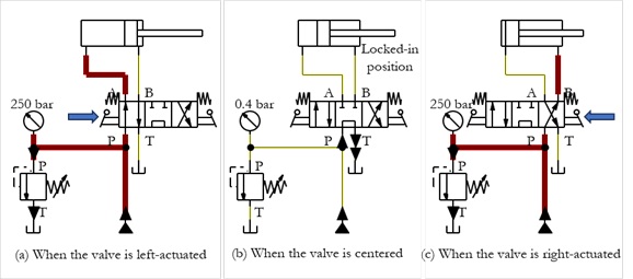
Figure 3 | Multiple positions of a hydraulic circuit with a hydraulic cylinder controlled by a 4/3-way tandem-centre valve
The left-actuated position of the valve can direct pressurized fluid to one side of a hydraulic cylinder, enabling forward motion of the cylinder, as shown in Figure 3(a).
The right-actuated position of the valve can direct pressurized fluid to the opposite side of a hydraulic cylinder, enabling the cylinder’s return motion, as shown in Figure 3(c).
When the valve is in its neutral position, the working ports are blocked. Pressures on both sides of the cylinder can be trapped, and the cylinder remains hydraulically locked in position. At the same time, the pump is unloaded to the tank, and the pump pressure drops drastically. Energy consumption also decreases, saving energy during a long-duration operation.
Limitations of the Circuit: When the pump is unloaded in the valve’s neutral position, other actuators cannot be connected to the pump. That is, a circuit with a tandem-centre valve is suitable only for a one-pump-one-cylinder circuit.
If multiple hydraulic cylinders are involved, the pump must be connected to the tank through the series-connected internal bypass (Port P to port T) connections of the associated tandem-centre directional control valves.
Additionally, the cylinder creeps due to clearances in the directional control valve. For safety-critical or zero-drift applications, engineers must add external pilot-operated check valves or counterbalance valves to positively lock the fluid.
Series Circuit Compatibility: The P to T internal passages in the tandem centre positions of multiple stacked 4/3-way valves can be connected in series to route the pump flow to the tank. This concept is explained with a circuit in the following section.
A Basic Circuit for Controlling Multiple Hydraulic Cylinders Using 4/3-way Tandem-Centre Valves
Here is the circuit layout for a series tandem circuit, followed by a step-by-step explanation of its operation.
The circuit shows two cylinders controlled by two 4/3-way tandem-centre valves, with their P-to-T internal passages connected in series. A fixed-displacement pump is connected to the P port of the first valve, and the T port of the second valve is connected to the tank.
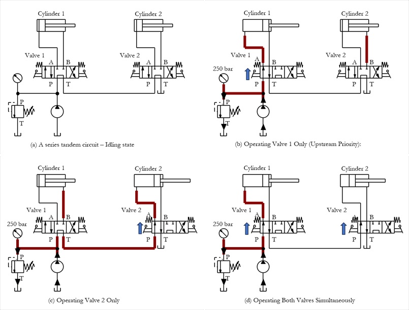
Figure 4 | The series tandem circuit diagram
Idling State: When all the tandem-centre valves (V1 and V2) are in the neutral position, the pump flow passes through the valves’ internal bypass channels and safely returns to the tank, as shown in Figure 4(a). The pump unloads at very low pressure, preventing heat buildup. All connected cylinders are hydraulically locked in position.
Operating Valve 1 Only (Upstream Priority): When an operator shifts Valve 1, as shown in Figure 4(b), the valve’s internal bypass channel closes. The pump flow is directed to cylinder 1, providing full pump flow and pressure for its operation.
Operating Valve 2 Only: The pump flow is directed to cylinder 2 through Valve 1’s internal bypass, providing full pump flow and pressure for its operation, as shown in Figure 4(c).
Operating Both Valves Simultaneously: If both Valve 1 and Valve 2 are shifted simultaneously, Valve 1 blocks the bypass channel, building pressure for Cylinder 1, as shown in Figure 4(d). Because Valve 1’s bypass is blocked, Valve 2 loses its primary high-pressure fluid supply and receives only the exhaust fluid returning from Cylinder 1. Valve 1 has absolute priority. Cylinder 2 will either move on Cylinder 1’s exhaust fluid or stop entirely if the load on Cylinder 2 requires more pressure than Cylinder 1’s return line can provide.
Note: Consider another possible scenario: Press Valve 2 continuously to fully extend Cylinder 2. Then, press Valve 1 to extend Cylinder 1. The fluid exiting Cylinder 1 flows to the pressurised piston side of Cylinder 2. A large force exerted by the differential Cylinder 1 on the trapped fluid can intensify the pressure in the line.
Engineering Note 1
(1) In systems requiring simultaneous operation of multiple actuators safely, engineers often select through-centre directional valves instead of series-connected tandem-centre valves to avoid pressure intensification and flow starvation.
(2) When multiple tandem-centre valves are linked, their internal flow paths restrict fluid, with each adding pressure drop. Multiple stacked valves can generate 20-30 bar or more backpressure from neutral routing.
Through-centre Directional Control Valve Circuit
To avoid the pressure intensification in the series-connected 4/3-way tandem-centre valves for controlling Cylinder 1 and Cylinder 2, a through-centre configuration with valves V1 and V2, as shown in Figure 5, can be used. In the neutral position of the valves, the pump flow is unloaded to the tank at essentially low pressure, reducing heat build-up and saving energy.
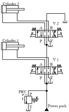
Figure 5 | Control of multiple hydraulic cylinders using through-centre directional control valves
When Valve V1 is actuated to the left envelope position, port P is connected to port A, and port B is connected to tank port T. The piston side of Cylinder 1 receives pump flow through the P to A connection, and the piston rod side returns flow to the tank independently through the B to T connection (not through the center configuration path). As a result, Cylinder 1 extends. At the same time, Valve 2 is disconnected from the pump.
Similarly, when Valve V2 is actuated to the left envelope position, Cylinder 2 extends. At the same time, the center configuration line is disconnected from the tank.
Assume Valve V2 is continuously actuated to fully extend Cylinder 2. Then, actuating Valve V1 (with Valve V2 still actuated) to extend Cylinder 1 will not cause pressure intensification because the return flow from Cylinder 1 is independently relieved through the B-to-T connection of Valve V1.
Engineering Advantage: Because each actuated valve returns its exhaust fluid directly to the tank rather than through another valve’s centre passage, pressure intensification is avoided and multiple actuators can operate more independently.
Note: Through-centre directional control valves will be discussed in greater detail in a future article.
Applications of 4/3-way Tandem-centre Valves
The tandem-centre configuration is used to hold a hydraulic cylinder or load in position for long duration while the valve is in the neutral position, to let the pump unload fluid safely back to the reservoir to reduce system heat and save power, and to supply fluid power in a series connection to multiple valve blocks on a single pump. These functions are briefly explained below.
Typical Applications:
- Hydraulic presses
- Hydraulic lifts
- Front-end loaders
- Backhoes
- Excavators
- Agricultural machinery
- Material handling equipment
Engineering Note 2:
(1) Tandem-centre valves should not be used in systems such as hydraulic motor drives or vehicle steering, where the actuator needs to coast or spin to a stop naturally when centreed, rather than coming to an abrupt hydraulic halt.
(2) Tandem-centre valves should not be used in high-precision load-holding applications subjected to heavy, continuous external loads or drifting forces, where absolute leak-free static locking (with double-pilot check valves and 4/3-way float-centre valves) is mandatory.
Advantages and Limitations
Advantages and limitations of tandem-centre valves are summarized in Table 3.
Table 3 | Advantages and disadvantages of 4/3-way tandem centre valve
| Advantages | Limitations |
| ✔ Load holding while idling ✔ Pump unloading ✔ Low heat generation ✔ Energy saving ✔ Series connection | ✘ Cylinders cannot be floated ✘ Cylinders may creep due to micro-leakage ✘ Single actuator constraint ✘ Cumulative backpressure in series tandem connection ✘ Unsuitable for hydraulic motors requiring freewheeling |
When Should You Choose a Tandem-Centre Valve?
Use tandem-centre valves when:
✔ press or lift cylinders must remain locked in position
✔ energy savings are required during a single long-duration operation
✔ energy savings are required in a multiple-actuator circuit operating one actuator at a time
✔ a fixed-displacement pump is used
Avoid using tandem-centre valves when:
✘ cylinders must float
✘ hydraulic motors should stop smoothly
Typical Machines Using Tandem-Centre Valves
The tandem-centre configuration is used to hold a hydraulic cylinder or load stationary in the neutral position while letting the pump to route fluid safely back to the reservoir to reduce system heat and save power, and to supply fluid power in a series connection to multiple valve blocks on a single pump. Table 4 summarizes machines and their tandem components.
Table 4 | Summary of machines and their tandem components
| Machine | Why Tandem Centre? | Tandem Component |
| Tractor | Holds loader while unloading pump | Loader lift cylinder |
| Front loader | Holds bucket position during pauses | Lift cylinder |
| Harvester | Holds cutting head during transport | Lift cylinder |
| Backhoe | Holds boom or dipper during pauses | Boom cylinder |
| Excavator | Holds boom while engine idles | Boom cylinder |
| Forklift | Holds forks at selected height | Lift cylinder |
| Press | Holds ram at any position | Press cylinder |
Conclusion
The tandem-centre configuration of a 4/3-way hydraulic valve is particularly suitable when a cylinder must hold position for an extended period while conserving energy. However, because the valve cannot float a cylinder or stop a motor smoothly, it should be selected only after carefully considering the application requirements. Understanding the operating characteristics of each centre configuration enables engineers to select the most appropriate valve for reliable and safe hydraulic system operation.
Key Takeaways
✔ Blocks both actuator ports in the neutral position.
✔ Unloads the pump directly to the tank.
✔ Holds hydraulic cylinders in position.
✔ Reduces heat generation and energy consumption.
✔ Ideal for fixed-displacement pump systems.
By
Joji Parambath
About the Author
Joji Parambath is a fluid power engineer, author, and corporate trainer with more than 25 years of experience in hydraulics, pneumatics, and industrial automation. He is the founder of Fluidsys Training Centre Pvt. Ltd., Bangalore, and the author of numerous engineering books on fluid power systems.
References:
Books
1. Book on ‘Hydraulic Circuits – Identification of Components and Analysis’ by Joji Parambath
2. Book on ‘Industrial Hydraulic Systems and Circuits -Basic Level (In the SI Units)’ by Joji Parambath
3. Book on ‘Industrial Hydraulics -Basic Level (In the English Units)’ by Joji Parambath
Manufacturer Information
4. Information on ‘Tandem Centre Directional Control Valve’, Hebei Longshengtengyu Pump Industry Co., Ltd., Jichangzhuang Village, Ningjin County, Xingtai City, Hebei, China
5. Information on ‘Directional Hydraulic Valve Mid-Position (Neutral) Functions: O, H, M, Y’, No. 35, Jinda Road, Humen Town, Dongguan City, Guangdong Province, China
Articles
Article on ‘Reasons to Avoid Using Tandem Centre Valves in Series’ by Corey Rasmussen, published on the Mentored Engineer Durham website
Read More…

Hydraulic Circuits – Identification of Components and Analysis by Joji Parambath

Industrial Hydraulic Systems and Circuits -Basic Level (In the SI Units) by Joji Parambath
Practical Book: Industrial Hydraulics by Joji Parambath
You can easily find a complete list of books written by Joji Parambath on the Joji Books website.
Disclaimer of Liability
All content featured in this blog is for educational purposes. Fluidsys does not assume responsibility for designs based on content posted here. Only qualified personnel should be permitted to design, develop, install, and work on hydraulic equipment. Qualified personnel are those authorized to design, develop, commission, ground, and tag circuits, equipment, and systems in accordance with established safety practices and standards.


Leave a comment