
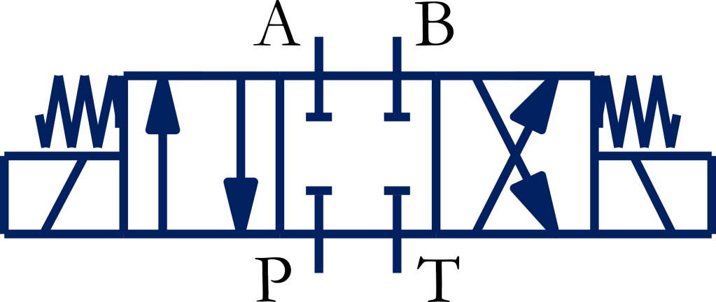
[Part 3 of the 4/3-Way Valve Centre Configuration Series]
Industrial presses, lifts, clamping fixtures, and injection moulding machines often require an actuator to remain in position for extended periods. The all-closed-centre configuration of a 4/3-way directional control valve blocks all four ports in the neutral position, thereby preventing intentional flow through the valve. However, a standard spool-type valve is not a leakage-free load-holding device, and additional load-holding or safety devices may be required depending on the application. A hydraulic circuit using this valve can also result in excessive heat generation and energy loss. This article explains how the valve works, why it is used, and when it should be selected. It also discusses important considerations for load holding and safety, as well as alternative circuits to overcome heat generation and energy loss.
Construction
The cross-sectional view and symbol of a hydraulic 4/3-way all-closed-centre valve are shown in Figures 1(a) and 1(b). The valve has four ports and three switching positions. It can be actuated manually or electrically via solenoids. When no other actuating force is present, the valve snaps to the centre position via springs.
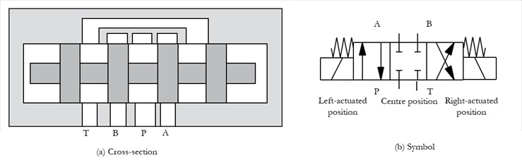
Figure 1 | 4/3-way all-closed-centre valve
Neutral Position
In the neutral (centre) position, all four ports are internally blocked, as shown in Figure 1. Blocking the actuator ports prevents intentional flow through the directional control valve and can help maintain the actuator position. However, a conventional spool-type valve has internal leakage, so the valve alone should not be considered a leakage-free or positive load-holding device. Where prolonged or safety-critical load holding is required, suitable load-holding devices should be incorporated into the circuit.
Principle of Operation
The positions, connections, and functions of the valve in the left-actuated, centre, and right-actuated positions are shown in Table 1.
Table 1 | A hydraulic 4/3-way all-closed-centre valve
| Left-actuated position | Centre (Neutral) position | Right-actuated position |

| Valve Ports: P – Pressure port T – Tank port A & B – Working ports (Imagine the ports are fixed while valve positions change) | ||
| P -> A B -> T | P, A, B, T -> Blocked | P -> B A -> T |
| A connected cylinder extends. | The cylinder is hydraulically blocked by the directional valve, subject to internal leakage and other circuit effects. In a fixed-displacement pump system, the pump forces fluid to other applications or across the main relief valve. | The cylinder retracts. |
Logic Diagram
Figure 2 highlights the concepts for the valve’s neutral position, as presented in the previous section.
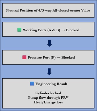
Figure 2 | Logic diagram illustrating the fundamental principles of all-closed-centre position.
Why Choose an All-Closed-Centre Valve?
In an all-closed-centre 4/3-way valve, ports A and B are blocked in the neutral position. Consequently, pressure can be trapped in the actuator circuit, helping to maintain the actuator position when the valve is shifted to neutral. However, the internal leakage of a conventional spool valve can permit gradual actuator drift. Therefore, where accurate or prolonged load holding is required, the directional control valve (probably float-centre configuration) should be supplemented with an appropriate load-holding device.
At the same time, the blocked pump port allows a single pump to serve multiple independent valve sections or actuators. At the same time, the pump flow is available for other independent operations. All-closed-centre valves are optimal for applications requiring multiple independent operations and precise load positioning in a neutral or intermediate state, such as construction equipment, cranes, vertical lifts, and clamping mechanisms.
Because the valve blocks pump flow in the neutral position, the system’s pump line remains fully pressurized at all times.
When used with a variable-displacement, pressure-compensated pump, a closed-centre valve operates efficiently.
Key Engineering Concepts
Let us start by becoming familiar with the key terms and conditions that apply to actuators controlled by all-closed-centre valves before we move on to their applications.
Cylinder Blocking: A condition in which the directional control valve blocks the actuator ports, trapping pressure in the cylinder circuit and restricting actuator movement. The actual ability to remain stationary depends on valve leakage, cylinder leakage, load characteristics, and any additional load-holding devices.
Load Holding: The ability of a hydraulic system to maintain an actuator or load in a stationary position under specified conditions. Depending on the application, this may require dedicated load-holding devices in addition to the directional control valve.
Spool Leakage: Internal fluid bypass through microscopic clearances in standard hydraulic spool valves.
Cylinder Creep: The slow movement or drift of a hydraulic cylinder over time due to internal leakage. A hydraulic system designer should consider cylinder drift when engineering a hydraulic system to hold a heavy load safely for long periods.
Heat/Energy Loss: Constant blockage of the pump flow forces fluid across the main relief valve in fixed-displacement systems, generating heat and wasting energy if the system is held in neutral too long.
Pressure Compensation: A pump control method that automatically adjusts pump displacement to maintain a preset system pressure while minimizing energy loss.
A Basic Circuit for the Control of a Hydraulic Cylinder by a 4/3-way All-Closed-Centre Valve
Figure 3(b) shows the normal position of the circuit for controlling a hydraulic cylinder, intended for long-duration operation, using an all-closed-centre valve. A powerpack with a fluid-filled tank and a fixed-displacement pump supplies the system with fluid. Although a fixed-displacement pump is shown for simplicity, a variable-displacement pressure-compensated pump is generally preferred in industrial applications.
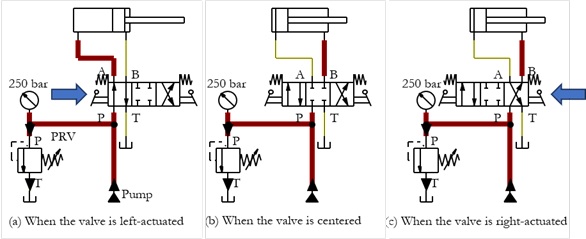
Figure 3 | Multiple positions of a hydraulic circuit with a hydraulic cylinder controlled by a 4/3-way valve with all-closed centre
The left-actuated position of the valve can direct pressurized fluid to one side of a hydraulic cylinder, enabling forward motion of the cylinder, as shown in Figure 3(a).
The right-actuated position of the valve can direct pressurized fluid to the opposite side of a hydraulic cylinder, enabling the cylinder’s return motion, as shown in Figure 3(c).
When the valve is in its neutral position, the working ports are blocked. Pressure can therefore be trapped on both sides of the cylinder, restricting its movement. However, a conventional spool valve has internal leakage, so gradual cylinder drift may occur over time. Where the cylinder must remain stationary for an extended period or where the load is safety-critical, an appropriate load-holding arrangement should be provided.
This configuration, with the pressure port blocked in the centre position of each valve, is best suited for the independent operation of multiple actuators.
Because the valve blocks the pump flow in the neutral position, the system’s pump line remains fully pressurized at all times.
When paired with a variable-displacement, pressure-compensated pump, a closed-centre valve operates efficiently.
Limitations of the Circuit: When the pump flow through the valve is blocked in the neutral position, the flow is diverted through the system pressure relief valve. As a result, heat develops and the system’s energy consumption increases.
Core Precautions While Holding Heavy Loads
An all-closed-centre directional control valve can restrict actuator movement and is often used as part of hydraulic circuits for lifting and load-holding applications. However, the directional valve alone should not be assumed to provide safe or positive load holding, particularly for suspended or safety-critical loads. Appropriate load-holding and safety devices must be selected according to the application. Some important precautions are highlighted below:
Valve and Circuit Protection
- Install pilot-operated check valves for cylinders.
- Install brake valves for hydraulic motors directly at the motor’s ports.
- Add cross-port relief valves to hydraulic motor circuits to absorb high shock loads during stopping.
- Use thermal relief valves to handle fluid expansion caused by rising ambient temperatures in trapped lines.
Operational Safety
- Set pressure-relief valves safely below the maximum ratings of cylinders, hydraulic motors, and hoses.
- Bleed all trapped air from the system to prevent spongy movement and sudden load jumps.
- Check seals and fittings regularly to detect internal or external leaks that cause load drift.
A Basic Hydraulic Circuit for Controlling Multiple Cylinders Using 4/3-way All-Closed-Centre Valves
Figure 4(a) shows a circuit for controlling two cylinders (Cylinder 1 and Cylinder 2) using two 4/3-way all-closed-centre valves (Valve 1 and Valve 2). A fixed-displacement pump is connected to the P ports of the valves. The pump must deliver the required flow to the actuators. The pressure is set using a pressure relief valve.
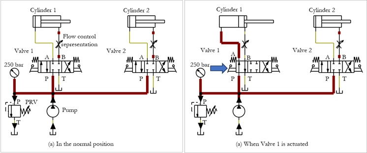
Figure 4 | Operating conditions of a two-cylinder circuit using all-closed-centre valves.
When Valve 1 is actuated, the pump flow is directed to the piston side (cap-end) of Cylinder 1, and the return flow is directed to the tank, as shown in Figure 4(b). The cylinder then extends.
Similarly, Cylinder 2 can be independently controlled using Valve 2.
Energy-saving Alternatives for Hydraulic Circuits with Closed-centre Valves
The use of all-closed-centre valves in a hydraulic system leads to heat buildup and energy loss. Various options, including advanced pump controls and energy recovery methods, are available to overcome these issues. Some of them are highlighted below:
Advanced Pump Controls
- Variable-Displacement Pumps: Adjust flow output dynamically rather than dumping excess fluid through a relief valve.
- Load-Sensing (LS) Systems: Match pump pressure and flow to the highest load demand.
Energy Recovery Method
- Accumulators: Store excess potential or kinetic energy during lowering or braking, then reuse it.
Engineering Solutions for Reducing Heat Generation in All-Closed-Centre Hydraulic Systems
Several engineering solutions can be used to reduce heat generation and energy loss in hydraulic systems employing all-closed-centre directional control valves. Three commonly used approaches—an unloading valve, a pressure-compensated variable-displacement pump, and a load-sensing system—are illustrated in Figure 5.
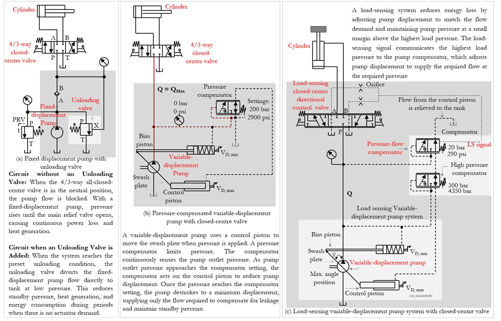
Figure 5 | Engineering solutions for reducing heat generation and energy loss in hydraulic systems using all-closed-centre directional control valves
Summary
Fixed-displacement Pump:
Excess flow → Unloading valve → Tank
↓
Variable-displacement Pump:
Pressure rises → Pump destrokes
↓
Load-sensing System:
Load demand → LS signal → Pump adjusts displacement
Comparison of Energy-Saving Methods
Table 2 gives a comparison of energy-saving methods.
Table 2 | Comparison of energy-saving methods
| Solution | Complexity | Energy efficiency* | Typical applications |
| Unloading valve | Low | Good | Fixed-displacement industrial systems |
| Variable-displacement pump | Medium | Very good | Industrial and mobile hydraulics |
| Load-sensing system | High | Excellent | Modern mobile hydraulics |
*Note: Relative ratings are indicative and depend on system design and operating conditions.
Engineering Recommendation
For new hydraulic systems employing all-closed-centre directional control valves, variable-displacement pressure-compensated pumps are generally the preferred solution because they significantly reduce standby heat generation and improve overall energy efficiency. Unloading valves provide an economical alternative when fixed-displacement pumps are used.
Flow Control in a Single-pump, Multi-actuator Hydraulic System
Flow control in a single-pump, multi-actuator hydraulic system can be achieved by dividing or metering the shared pump output with flow control valves, priority valves, or proportional/servo valves. These devices direct precise volumes of fluid to each actuator, allowing their speeds to be managed independently despite sharing the flow from a single pump.
Methods of Flow Control
- Throttle and Needle Valves: Use an adjustable orifice or throttle valve to restrict flow to individual branches, slowing an actuator by diverting excess pump flow through a pressure relief valve or pressure compensator.
- Pressure-compensated Flow Controls: Maintain a steady flow rate to an actuator even when external loads or system pressures change.
- Priority Flow Control Valves: Deliver a fixed, guaranteed flow rate to a primary critical circuit (such as steering) and route any excess fluid to secondary utility actuators.
- Rotary Flow Dividers: Mechanically split a single pump stream into multiple equal or proportional fluid streams to power separate actuators synchronously.
- Proportional Controls: Use sensors and programmable logic controllers (PLCs) to dynamically command electro-hydraulic proportional/servo valves for precise, real-time speed adjustment.
Applications of 4/3-way All-Closed-Centre Valves
A 4/3-way all-closed-centre hydraulic valve blocks fluid flow from the pump and traps fluid in all cylinder ports when centreed. This holds cylinders securely in place, prevents drift with additional load-locking valves, saves energy with valve-controlled or pump-controlled mechanisms, and enables safe load-holding in presses, cranes, and clamping systems.
Key Industrial Applications
- Hydraulic presses: Holds the ram firmly in a mid-stroke position without dropping the load.
- Cranes and lifts: Stops and safely holds heavy suspended loads when the control lever is neutral.
- Clamping fixtures: Maintains high clamping pressure on workpieces during machining without running the pump.
- Injection moulding machines: Locks mould positions securely during high-pressure injection phases.
Engineering Note:
(1) A 4/3-way all-closed-centre hydraulic valve blocks all ports in the neutral position. When used with fixed-displacement pumps, an all-closed-centre valve requires a suitable unloading arrangement; otherwise, continuous relief valve operation can cause overheating, energy loss, and unnecessary pump loading.
(2) A 4/3-way closed-centre hydraulic valve should not be used with a hydraulic motor when smooth deceleration or manual freewheeling of the motor is required.
Advantages and Limitations
Advantages and limitations of all-closed-centre valves are summarized in Table 3.
Table 3 | Advantages and limitations of 4/3-way all-closed-centre valves
| Advantages | Limitations |
| ✔ Multiple actuators can be controlled ✔ Actuator ports can be blocked to restrict movement | ✘ Cylinders cannot be floated ✘ Cylinders may creep due to micro-leakage ✘ Hydraulic motors cannot be stopped smoothly ✘ Hydraulic motors cannot freewheel ✘ Heat generation / Energy loss |
When Should You Choose an All-Closed-Centre Valve?
Use all-closed-centre valves when:
✔ press or lift cylinders must remain in position and the circuit includes appropriate load-holding provisions
✔ multiple actuators must be controlled independently
Avoid using all-closed-centre valves when:
✘ cylinders must float
✘ hydraulic motors should stop smoothly
✘ suspended or overrunning loads require positive load holding but the circuit has no suitable load-holding device
Typical Machines Using All-Closed-Centre Valves
The all-closed-centre configuration is used to hold a hydraulic cylinder or load stationary in the neutral position while allowing the pump to serve multiple valve blocks and actuators on a single pump. Table 4 summarizes the machines and their components.
Table 4 | Summary of machines using all-closed-centre valves
| Machine | Why all-closed Centre? | All-closed-centre component |
| Cranes | Used as part of hydraulic circuits for controlling suspended loads, together with suitable load-holding and safety devices. | Hoist cylinder or Luffing cylinder |
| Lifts | Used as part of hydraulic circuits for controlling suspended loads, together with suitable load-holding and safety devices. | Lift cylinder |
| Clamping fixture | Helps maintain actuator pressure and clamping position; suitable pressure- and load-holding provisions should be provided according to the application. | Clamping cylinder |
| Press | Helps maintain the ram position by blocking the actuator ports; additional load-holding provisions may be required depending on the application. | Press cylinder |
| Injection moulding machine | Helps maintain mould actuator position during the required phase of operation; application-specific safety and load-holding provisions may also be required. | Mould cylinder |
Conclusion
The all-closed-centre configuration of a 4/3-way valve is particularly suitable when actuator ports need to be blocked in the neutral position and multiple actuators must be controlled independently in a single-pump system. However, a conventional spool-type directional control valve should not be considered a leakage-free or positive load-holding device. Where a load must remain stationary for an extended period, particularly in suspended-load or safety-critical applications, appropriate load-holding and safety devices must be incorporated into the hydraulic circuit. Understanding the operating characteristics of each centre configuration enables engineers to select the most appropriate valve and supporting components for reliable and safe hydraulic system operation.
By
Joji Parambath
About the Author
Joji Parambath is a fluid power engineer, author, and corporate trainer with more than 25 years of experience in hydraulics, pneumatics, and industrial automation. He is the founder of Fluidsys Training Centre Pvt. Ltd., Bangalore, and the author of numerous engineering books on fluid power systems.
References:
Books
1. Book on ‘Hydraulic Circuits – Identification of Components and Analysis’ by Joji Parambath
2. Book on ‘Industrial Hydraulic Systems and Circuits -Basic Level (In the SI Units)’ by Joji Parambath
3. Book on ‘Industrial Hydraulics -Basic Level (In the English Units)’ by Joji Parambath
4. Book on ‘Hydrostatic Transmissions (HSTs) (In the SI Units)’
5. Book on ‘Concepts of Hydrostatic Transmissions (In the English Units)’
6. Book on ‘Load Sensing Hydraulic Systems (In the SI Units)’
7. Book on ‘Concepts of Load Sensing Hydraulic Systems (In the English Units)’
Articles
- Article on ‘A guide to selecting the right hydraulic flow control valve to optimise system performance and efficiency’, by Steve Skinner, WEBTECH, Milwaukee, USA
- Article on ‘Hydraulic Systems Safety Basics 101’, White House Products, Ltd. Kelburn Business Park, Port Glasgow, Renfrewshire, UK
- Article on ‘Hydraulic Valves, Gain Control of the Flow’, Power & Motion
- Article on ‘Load Holding Valves in Hydraulic Cranes’, by John Phillips, Warren Forensics, Irmo, SC
- Article on ‘What damage will be caused by overloading the hydraulic system? Avoid Costly System Failures and Downtime’, by Tech Team · Kintek Solution, Zhengzhou, China
- Article on ‘Your Guide to the Hydraulic Safety Relief Valve’, Ashley Estate,
Exmoor Avenue, Scunthorpe, North Lincolnshire, UK - Featured Article on ‘3 Ways to Reduce Hydraulic Shock’, Al Smiley, GPM Hydraulic Consulting, Machinery Lubrication August 2017.
Read More…

Hydraulic Circuits – Identification of Components and Analysis by Joji Parambath
Hydrostatic Transmissions (HSTs) (In the SI Units) by Joji Parambath
Concepts of Load Sensing Systems (In the English Units)
You can easily find a complete list of books written by Joji Parambath on the Joji Books website.
Disclaimer of Liability
All content featured in this blog is for educational purposes. Fluidsys does not assume responsibility for designs based on content posted here. Only qualified personnel should be permitted to design, develop, install, and work on hydraulic equipment. Qualified personnel are those authorized to design, develop, commission, ground, and tag circuits, equipment, and systems in accordance with established safety practices and standards.


Leave a comment