
[Part 5 of the 4/3-Way Valve Centre Configuration Series]
The centre position of a 4/3-way directional control valve determines how the pump, tank, and actuator ports are interconnected when the valve is in the neutral position. This directly influences pump unloading, actuator movement, load holding, heat generation, and the valve’s overall suitability for a particular application.
In addition to the commonly discussed centre configurations, specialised centre arrangements are also used for particular hydraulic functions. One example is the regenerative centre configuration, which is primarily used to achieve high cylinder extension speed.
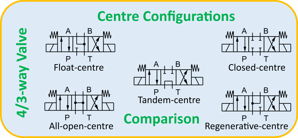
Figure 1 shows 4/3-way valves with many centre configurations.
4/3-way float-centre valve
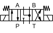
4/3-way tandem-centre valve
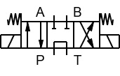
4/3-way all-closed-centre valve
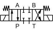
4/3-way all-open-centre valve
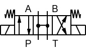
4/3-way regen. centre valve
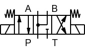
Figure 1 | 4/3-way valves with many centre configurations
A comparison of several centre configurations of the 4/3-way valve is presented in Table 1.
Table 1 | Comparison of 4/3-way hydraulic valve centre configurations
| Centre configuration | Configuration | Working | Best applications |
| Float-Centre | Actuator ports (A and B) connect to the tank (T), while the pump port (P) is blocked. | Floating / free movement: Connects the actuator ports to the tank, greatly reducing the pressure difference across the actuator and allowing external forces to move the actuator relatively freely. | Snow plow blades that must ride along the ground contour, dump truck bodies lowering under gravity, or hydraulic motors that need to coast or freewheel after the control valve is returned to neutral. |
| Tandem-Centre | Actuator ports (A and B) are blocked, while the pump port (P) connects directly to the tank (T). | Actuator load holding and pump unloading: -Blocks flow through the actuator ports, helping to maintain the actuator position, while directing idle pump flow to the tank at low pressure. -With a conventional spool valve, internal leakage may allow gradual actuator drift; additional load-holding devices may be required for prolonged or safety-critical load holding. | Mobile machinery, agricultural loaders, and tractor implement controls where actuator movement must be restricted while the pump is unloaded. Suitable load-holding devices may be required for prolonged or safety-critical load holding. |
| All-Closed-Centre | Pump (P), tank (T), and actuator ports (A and B) are all blocked. | Load holding and independent actuator control Pressure can be trapped in the actuator circuit, helping to maintain the actuator position when the valve is shifted to neutral. However, the internal leakage of a conventional spool valve can permit gradual actuator drift. Therefore, where accurate or prolonged load holding is required, the directional control valve should be supplemented with an appropriate load-holding device. Independent control of multiple actuators For fixed-displacement pump systems, a suitable unloading arrangement is required to prevent continuous relief-valve operation and excessive heat generation. A pressure-compensated variable-displacement pump is often preferred for efficient operation. | Industrial presses, clamping fixtures, or multi-actuator circuits running on a central variable-flow power unit |
| All-Open-Centre | All ports (P, T, A, and B) connect together in the neutral position | Motor smooth stopping, freewheeling, and pump unloading Unloads the pump to the tank while connecting both actuator ports to the tank. In motor applications, this can greatly reduce the pressure difference across the motor, allowing the driven load to coast or freewheel. | Hydraulic motor circuits where the driven load needs to coast or freewheel after the control lever is returned to neutral. |
| Regenerative-Centre | Connects the pump port (P) to both actuator ports (A and B), while blocking the tank port (T). | Connects the pump flow to both actuator ports while blocking the tank port. When applied to a double-acting cylinder, this connection can provide regenerative extension. During extension, oil discharged from the rod-end chamber is redirected to the cap-end chamber, where it combines with the pump flow. This regenerative action increases cylinder extension speed, but reduces the available extension force compared with conventional extension. | -High-speed cylinder extension during an approach stroke, such as the fast-forward stroke of an industrial press before the cylinder encounters the workpiece. -Certain cartridge-valve circuits, including bridge-type arrangements, where the centre connection is selected to achieve a specific control function. |
Advantages and Main Limitations of 4/3-way Centre Configurations
The main advantages and limitations are summarized in Table 2, providing a clear overview for your convenience.
Table 2 | Main advantages and limitations of 4/3-way centre configurations
| Centre configuration | Main advantage | Main limitation |
| Float-centre | Free movement / motor freewheeling | Cannot provide positive actuator locking |
| Tandem-centre | Pump unloading with actuator ports blocked | Fixed-pump systems; actuator leakage can cause drift |
| All-closed-centre | Independent control of multiple actuators | Standby losses with fixed-displacement pumps |
| All-open-centre | Motor freewheeling + pump unloading | Not suitable where actuator ports must remain blocked |
| Regenerative-centre | High cylinder extension speed | Reduced extension force |
How Should You Select the Centre Configuration?
The following guide provides a simplified approach to selection. The final centre configuration should always be selected according to the complete actuator, load, pump, control, and safety requirements of the application.
Do you need the actuator to move relatively freely in neutral?
Yes → Float-centre
Do you need actuator ports blocked but want to unload a fixed-displacement pump?
Yes → Tandem-centre
Do you need independent control of multiple actuators?
Yes → All-closed-centre
Does a hydraulic motor need to coast or freewheel?
Yes → All-open-centre
Do you need high cylinder extension speed than normal speed during the approach stroke?
Yes → Regenerative-centre
Important Engineering Note
The centre configuration of a directional control valve should not be confused with the load-holding capability of the complete hydraulic circuit. A blocked actuator port can restrict movement, but conventional spool valves have internal leakage. Suspended or safety-critical loads may therefore require dedicated load-holding and safety devices such as pilot-operated check valves, counterbalance valves, mechanical brakes, or other application-specific arrangements.
Summary of Pump Behaviour
The summary of pump conditions in the neutral positions of 4/3-way valves is provided in Table 3.
Table 3 | Summary of pump behaviour
| Centre configuration | Pump condition in neutral |
| Float-centre | P blocked |
| Tandem-centre | P → T |
| All-closed-centre | P blocked |
| All-open-centre | P → T |
| Regenerative-centre | P → A and B; T blocked |
Note: There are many other centre configurations and specialised spool arrangements for 4/3-way directional control valves. They are beyond the scope of this article.
Main Highlights
✔ A centre configuration determines how P, T, A and B are interconnected in the neutral position.
✔ A float-centre configuration permits relatively free actuator movement.
✔ A tandem-centre configuration combines blocked actuator ports with pump unloading.
✔An all-closed-centre configuration facilitates independent actuator control but requires appropriate pump-flow management.
✔ An all-open-centre configuration can be useful for hydraulic motor freewheeling and pump unloading.
✔ A regenerative-centre configuration can provide high cylinder extension speed at the expense of available extension force.
✔ Centre configuration alone does not guarantee positive or safe load holding; application-specific load-holding and safety devices may be required.
By
Joji Parambath
About the Author
Joji Parambath is a fluid power engineer, author, and corporate trainer with more than 25 years of experience in hydraulics, pneumatics, and industrial automation. He is the founder of Fluidsys Training Centre Pvt. Ltd., Bangalore, and the author of numerous engineering books on fluid power systems.
References:
Parts 1 to 4 of the 4/3-Way Valve Centre Configuration Series posted by the same Author
Read More…

Hydraulic Circuits – Identification of Components and Analysis by Joji Parambath
Hydrostatic Transmissions (HSTs) (In the SI Units) by Joji Parambath
Concepts of Load Sensing Systems (In the English Units)
You can easily find a complete list of books written by Joji Parambath on the Joji Books website.
Disclaimer of Liability
All content featured in this blog is for educational purposes. Fluidsys does not assume responsibility for designs based on content posted here. Only qualified personnel should be permitted to design, develop, install, and work on hydraulic equipment. Qualified personnel are those authorized to design, develop, commission, ground, and tag circuits, equipment, and systems in accordance with established safety practices and standards.


Leave a comment