
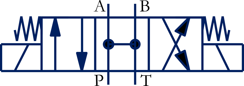
[Part 4 of the 4/3-Way Valve Centre Configuration Series]
A hydraulic motor driving a high-inertia load often requires a valve that enables it to coast to a stop when the valve’s actuating lever is released. At the same time, associated pumps should unload at zero pressure to reduce heat loss and power consumption. An all-open-centre configuration of a 4/3-way (directional control) valve provides these capabilities by connecting both actuator ports and the pump port to the tank. This article explains how the valve works, why it is used, and when it should be selected.
Construction
The cross-sectional view and symbol of a hydraulic 4/3-way all-open valve are shown in Figures 1(a) and 1(b). The valve has four ports and three switching positions. It can be actuated manually or electrically using solenoids. The valve snaps to the centre position using springs when no other actuating force is present.
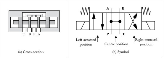
Figure 1 | 4/3-way all-open-centre valve
Neutral Position
In the neutral (centre) position of the hydraulic valve, the pump port (P) and the actuator ports (A and B) are internally connected to the tank port (T), as shown in Figure 1.
By connecting both motor ports to the tank, hydraulic pressure cannot be trapped on either side of the actuator. Consequently, the motor is not hydraulically locked and can respond freely to external forces. Therefore, the motor is not subjected to a sudden hydraulic lock, thereby preventing pressure spikes and allowing the load’s inertia to dissipate naturally. This centre position allows a connected hydraulic motor to freewheel.
At the same time, when the pump port is connected to the tank port, the pump can unload into the tank at minimum pressure, thereby reducing power consumption.
Principle of Operation
The positions, connections, and functions in the left-actuated, centre, and right-actuated positions of the valve are given in Table 1.
Table 1 | A hydraulic 4/3-way all-open-centre valve
| Left-actuated position | Centre (Neutral) position | Right-actuated position |

| P – Pressure port T – Tank port A & B – Working ports (Imagine the ports are fixed while valve positions change) | ||
| P -> A B -> T | P, A, B -> T | P -> B A -> T |
| A connected cylinder extends | The motor stops smoothly and can freewheel | The cylinder retracts |
| A connected hydraulic motor rotates in one direction | Pump is unloaded to the tank at minimum pressure, thereby reducing power consumption. | The motor rotates in the opposite direction |
Logic Diagram
Figure 2 highlights the concepts for the valve’s neutral position presented in the previous section.
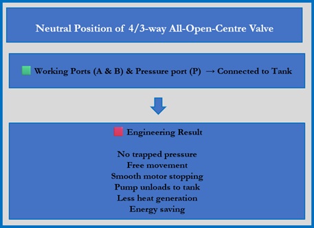
Figure 2 | Logic diagram illustrating the fundamental principles of all-open-centre valves.
Why Choose an All-Open-Centre Valve?
In tandem-centre and closed-centre 4/3-way valves, ports A and B are blocked in the neutral position. Consequently, the associated motor lines may trap pressure when the valve is shifted to its neutral position. This results in jerky movement when a motor attempts to halt, and freewheeling the motor becomes unfeasible.
An all-open-centre valve in its centre position, with ports A and B connected to the tank T, can provide a smooth stop for a hydraulic motor and allow the motor’s output shaft to spin freely with minimal resistance.
At the same time, with the pump port connected to the tank port, the pump can unload to the tank at minimum pressure, thereby reducing power consumption and energy loss.
Key Engineering Concepts
Let’s start by getting familiar with the key terms and conditions that relate to actuators controlled by all-open-centre valves, before we move on to their applications.
Smooth Stop of a Hydraulic Motor: An abrupt stop of a hydraulic motor coupled to a high-inertia load can cause shock pressures that can crack pipes, ruin hoses, and wear out motor parts. Therefore, it is necessary to stop the motor smoothly. That is, a smooth stop is a controlled deceleration of the motor that prevents sudden jerks, loud noises, and damaging pressure spikes as the motor comes to a stop. It is achieved using special components such as all-open-centre valves or cross-port relief valves.
Freewheeling of a Hydraulic Motor: A hydraulic motor can be used to drive loads in industrial and mobile systems in the working mode or freewheeling mode. In the working mode, the associated hydraulic motor can drive heavy loads at lower speeds. For example, a hydraulic motor can move the vehicle off-road for high traction. In the freewheeling mode, the motor shaft can rotate freely with minimal resistance and power loss. Therefore, the motor’s drive shaft can spin at high speeds when subjected to external forces.
Pump Unloading: In the valve’s neutral position, a pump bypasses fluid to the tank at near-atmospheric pressure, reducing heat and saving energy when work is paused.
A Basic Circuit for the Control of a Hydraulic Motor by a 4/3-way All-open-centre Valve
Figure 3(b) shows the normal position of the circuit for controlling a hydraulic motor using an all-open-centre valve. A powerpack with a fluid-filled tank and a fixed-displacement pump (A variable-displacement pump is even better) supplies the fluid to the system.
The left-actuated position of the valve can direct pressurized fluid to one side of a hydraulic motor, enabling rotation in one direction (say, anticlockwise direction), as shown in Figure 3(a).
The right-actuated position of the valve can direct pressurized fluid to the other side of a hydraulic motor, enabling rotation in the other direction (i.e., clockwise), as shown in Figure 3(c).
When the valve is in its neutral position, the motor ports are connected to the tank, and fluid from both ports vents freely to the tank, preventing fluid from trapping pressure on either side of the motor. This helps the motor to come to a smooth stop without jerks or shocks. Further, the motor can freewheel without making any internal contact with the cam, allowing external forces to move it freely.
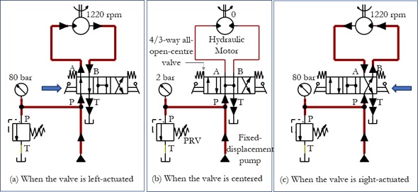
Figure 3 | Multiple positions of a hydraulic circuit with a hydraulic motor controlled by a 4/3-way all-open-centre valve
Why a Hydraulic Cylinder Drift Outward When Connected to a 4/3-way All-open-centre Valve?
When an all-open-centre valve is connected to a differential cylinder in a hydraulic system powered by a fixed-displacement pump, a low back pressure fills both sides of your cylinder simultaneously in the centre position of the valve. The net forward force generated by the cylinder overcomes the internal seal friction, causing the cylinder to slowly drift outward.
Applications of 4/3-way All-open-centre Valves
The all-open-centre configuration is particularly useful in hydraulic motor applications where smooth stopping, freewheeling, or pump unloading is required. Typical applications are briefly discussed below.
Motor Applications
The float centre position, with the actuator ports (A and B) internally connected to the tank port (T), allows a running hydraulic motor coupled with a high-inertia load and connected to the valve to stop smoothly by quickly relieving the fluid pressure in the motor, thus preventing pressure spikes and motor jerks.
An all-open-center valve can also be used to control freewheeling by connecting both motor ports directly to the tank and reducing the pressure difference across the motor when the valve is in its center position. Applications for freewheeling include trailers, graders, harvesters, mining, and hoisting. For example, the all-open-centre valve connected to the hydraulic motor in a winch control system allows the winch drum, coupled to the motor, to freewheel so that an operator can pull the associated cable.
Choose an all-open-centre valve for simple, single-actuator machines powered by a low-cost fixed-displacement pump to unload at zero pressure when idling, and to stop the associated hydraulic motor smoothly and spin the motor’s output shaft freely.
Limitations: An all-open-centre valve can provide hydraulic freewheeling, but it should not be relied upon as the sole means of securing a suspended load. (1) An all-open-centre valve cannot hold a suspended load in the valve’s neutral position. The load will immediately pull the cable out, causing the winch to drop uncontrollably. (2) Pulling the drum cable by hand while forcing a heavy hydraulic motor to spin creates substantial mechanical drag. It requires significantly more physical effort to pull the line out than a mechanical clutch disconnect does.
Safety Precautions: To safely use an all-open-centre valve for free-wheeling, an external, spring-applied, hydraulically released mechanical brake should be integrated. This brake must be able to lock the drum manually or hydraulically when required to hold the load.
Important Consideration for High-inertia Loads
When an all-open-centre valve is used with a hydraulic motor driving a high-inertia or overrunning load, the motor may continue rotating after the directional valve is returned to neutral. The deceleration behaviour depends on the entire hydraulic circuit and load characteristics. Appropriate braking, counterbalance, relief, or other application-specific measures may therefore be required to control the stored kinetic energy and prevent excessive overspeed or pressure transients.
Advantages and Limitations
Advantages and limitations of all-open-centre valves are summarized in Table 3.
Table 3 | Advantages and disadvantages of 4/3-way all-open-centre valve
| Advantages | Limitations |
| ✔ Smooth motor stopping ✔ Freewheel capability ✔ Low shock ✔Allows fluid to flow freely when there is no demand for power ✔Reduces overall heat generation | ✘ Cannot hold suspended loads stationary ✘ Load can drift ✘ Additional load-holding valves are required ✘ Vulnerable to cavitation ✘ Limited power capability ✘ Not suitable for every hydraulic system |
When Should You Choose an All-open-centre Valve?
Use all-open-centre valves when:
✔ Hydraulic motors require smooth stopping
✔ Motors require freewheeling
✔ A low-cost fixed-displacement pump is desirable
✔ Simple single-motor circuits are used
✔ Machinery does not demand high power
Avoid using all-open-centre valves when:
✔ Cylinders must remain rigid
✔ Abrupt motor braking is required
Typical Machines Using All-open-centre Valves
Machines use hydraulic all-open-centre valves whenever cylinders or attachments must move freely following external counters without hydraulic resistance or hydraulic motors should stop smoothly and freewheel. Table 4 summarises machines and their floating components.
Table 4 | Typical Applications of All-Open-Centre Valves
| Machine | Application | Hydraulic component |
| Winch | Controlled free-spooling | Hydraulic motor |
| Trailer drive | Freewheeling / auxiliary traction | Wheel motor |
| Motor grader | Freewheeling of drive system | Hydraulic motor |
| Harvester | Freewheeling / controlled stopping | Hydraulic motor |
| Mining equipment | Smooth stopping of high-inertia loads | Hydraulic motor |
Conclusion
The all-open-centre configuration of a 4/3-way valve is particularly suitable where hydraulic motors require smooth stopping or freewheeling. However, because the valve cannot hold suspended loads in its neutral position, it should be selected only after carefully considering the application requirements and any necessary load-holding devices. Understanding the operating characteristics of each centre configuration enables engineers to select the most appropriate valve for reliable and safe hydraulic system performance.
By
Joji Parambath
About the Author
Joji Parambath is a fluid power engineer, author, and corporate trainer with more than 25 years of experience in hydraulics, pneumatics, and industrial automation. He is the founder of Fluidsys Training Centre Pvt. Ltd., Bangalore, and the author of numerous engineering books on fluid power systems.
References:
Books
1. Book on ‘Hydraulic Circuits – Identification of Components and Analysis’ by Joji Parambath
2. Book on ‘Industrial Hydraulic Systems and Circuits -Basic Level (In the SI Units)’ by Joji Parambath
3. Book on ‘Industrial Hydraulics -Basic Level (In the English Units)’ by Joji Parambath
Articles
1. Article on ‘What Is The Purpose Of Using A Directional Control Valve?’, POOCCA, Poocca Industrial Park, Shenzhen, China
Read More…

Hydraulic Circuits – Identification of Components and Analysis by Joji Parambath

Industrial Hydraulic Systems and Circuits – Basic Level (In the SI Units) by Joji Parambath
Industrial Hydraulics – Basic Level (In the English Units)
You can easily find a complete list of books written by Joji Parambath on the Joji Books website.
Disclaimer of Liability
All content featured in this blog is for educational purposes. Fluidsys does not assume responsibility for designs based on content posted here. Only qualified personnel should be permitted to design, develop, install, and work on hydraulic equipment. Qualified personnel are those authorized to design, develop, commission, ground, and tag circuits, equipment, and systems in accordance with established safety practices and standards.


Leave a comment